
Recent CNC Machine Woes and Changes - 35/04/2023
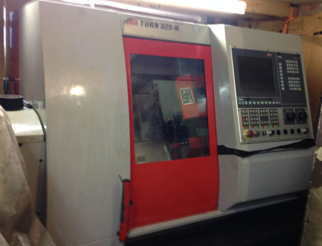
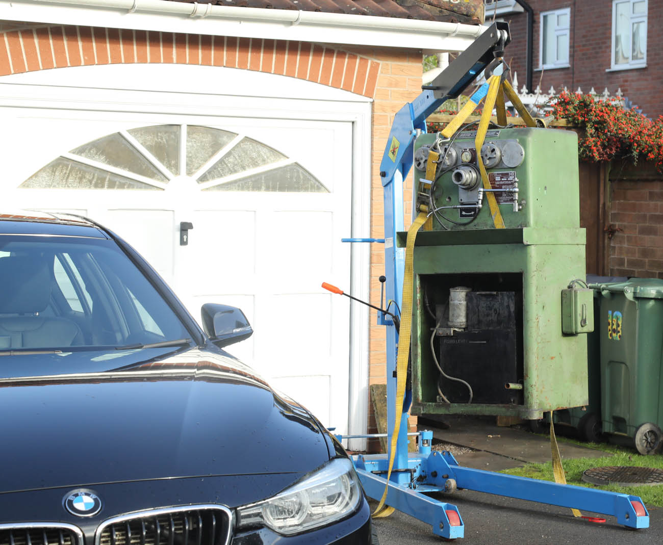
My main CNC Lathe Mill - an Austrian made Emco 325-II Lathe/Mill, purchased second hand from a small engineering company in Stevenage (home of the Vincent!), as delivered to me back in 2016
CNC lathes, mills and lathe/mills are wonderful things when they are working, but one of the occupational hazards of operating them - particularly the good quality ones, is that they need regular maintenance to keep them running at their best . . . and when they do decide to go wrong, it can quickly turn out to be a very expensive and time consuming process to get to the bottom of the issue and resolve thiem.
There is an old saying - 'You get what you pay for', and with my own limited experiance of engineering CNC machines - I would tend to agree, it is very easy to fall into the trap of buying a manufacturing machine that seems great value for money, either because it is from a cheaper brand, or a better branded machine that has seen better days, but no doubt about it - when a machine gets used day in, day out - evenually it will start to wear out and things will start to go wrong . . . that is just a natural fact of life
For myself - the last few months seems to have been a series of
seperate and unrelated machine failures and faults, which combined together have become a major distraction, with a great deal of 'down time' and - my time being spent working out how best to fix or replace.those failures, rather than making parts for old Norton motorcycles.
Unfortunately, as a one man band (well actually - it is my daugher and I, but she has not got much knowledge of the inside of CNC machines!), when things do go wrong - most of the investigateion and fault finiding is down to yours truly. I am fortunate to have a good relationship with the UK Emco branch, and they have always been willing to offer phone and email advice (great guys), but wtih them being based on a the South Coast, and my machine being in a space restricted workshop - it is normally more practical for me to do my own fault finding and fixing, if possible
Choosing To Run Your Own CNC Machine - And Finding One
As far as CNC equipment is concerned - In my own case, I am at the small end of the engineering and manufacturing industry - in fact pretty much a 'One Man Band' for the stuff I make myself.
In the 18 years or so I have been operating - I had mainly used other trusted CNC engineering compnaies close to me for the parts we offer - and formed close relationships with most these companies. But that being said - about 10 years ago I decided it might be good to buy a CNC lathe of my own
My father was an engineer by trade (pre-CNC of course) and I grew up with small lathes and other tools around me. We had some nice Myford lathes, but in my mid 20's I purchased and renovated an old ran down 1950's Smart and Brown tool room lathe (as by then having moved to my own place - my father was not happy about losing the best Myfford we shared!), as well as numerous other older tooling - all of which have given fantastic service since - a week rarely goes by when I dont end up needing to use the lathe - either for something on my own bikes - or for limited batches or 2nd op for parts we make.
However, I had spent all of my professional career at that time working in the IT Industry (the parts manufacture at that time still being a part time second business), and many of my earlier years were spent as a Programmer - and watching CNC machines in operation when visiting my own manufacturers, I became more aware that many of the programming skills required to write (2 dimensional - in the case of Turning/lathe programs) were probably not that far different from the days when I was programming myself - I was an RPG and Cobol programmer myself back in the 1980's, before moving to Unix systems.
.
So, I figured that it might be a bit of a Busman's holiday to learn G-Code (the almost universal underlying language of most lathe and mill machines) and have a go myself - allowing me the autonomy to make parts myself from my own patterns - and the flexibility to spend extra Set-up time on more complex parts, it being my own time after all - where it would not be commercially viable to do so with my other CNC partners, particularly knowing the batch size would be small.
With space and power requirements being a limiting factor (oh, and funding of course!), I knew pretty quickly I would need to purchase a second hand machine, as any machine of quality was likely to be in excess of the £30k'ish I had set aside - and really, as well as the normal 2-axis lathe capability, it would be great if I could find a machine with an additional 'C' or 'Y' axis - i.e. the ability to do milling operations on a workpiece, as well as turning.
Unfortunately - good quality machines capable of doing all that, with a small to medium footprint, and second hand are extremely hard to find - and good ones normally get snapped up, by word of mouth, before going on the general market.
Emco CNC - Recent Health Issues
I bought my main CNC Lathe/Mill - an Austrian Emco 325-II lathe with C-Axis Mill, back in 2016, but it had taken over a year of searching for something that met my rather finicky requirements, before I was lucky enough to be in the right place at the right time.
I had been talking to the Emco sales rep about their current range of (wonderful quality) 250 Turn machines - which had that all important feature of 'Live Tooling' C-Axis, and realising I could not afford to buy one (I believe they are about £85k at current prices, before tooling) - when shortly after, he contacted me to tell me about this older version, which might shortly be coming available, as the current owner was talking to Emco with a view to upgrading this and another Emco they owned - for a larger version
As mentioned, the model number of this machine was an Emco 325-II, and the significance of the '-II' (ie. the Mk2 version), was that this was Emco's first model to use C-Axis, and was the direct forerunnger of the 250 Turn, sharing the same chassis and Sauter tool head, just having a slightly less powerful main spindle motor - and of course an older version of the Siemens operating system. I was really pleased to find this out - as the current 250 Turn was on the very limit of my power capability, and i had already excluded the original 325 (Mk1) because it did not have Live tooling - so was over the moon to then find out they had made this interim model - albeit, in quite small numbers I believe.
I was able to visit the engineering company and talk to the owner a couple of days later, the machine looked well kept and the owner was a real gentleman (and Velocette owner, as it turned out!), and very qucily a deal was done to buy the machine, a small amount of tooling - and most importantly - two very expensive Live milling tools (one parallel, one 90 degree, see photograph), and the icing on the cake - a Rohm 5 inch pneumatic 3 jaw chuck, for when items were to large for the 5c collets - a very high quality and desirable piece of kit..
Before the macine was moved offsite - I also arranged for Emco to give the machine a full service, and replace the (strenghened) perspex door, with a new panel - as the screen was quite yellowed - a common fault with CNC perspex screens. The machine was delieverd to me (as per the first photograph) in late summer 2016 - and I was always grateful to the previous owner as I think I got a great deal, and they even cleaned it spotless before handing it over to me.
12 Tool Station Head
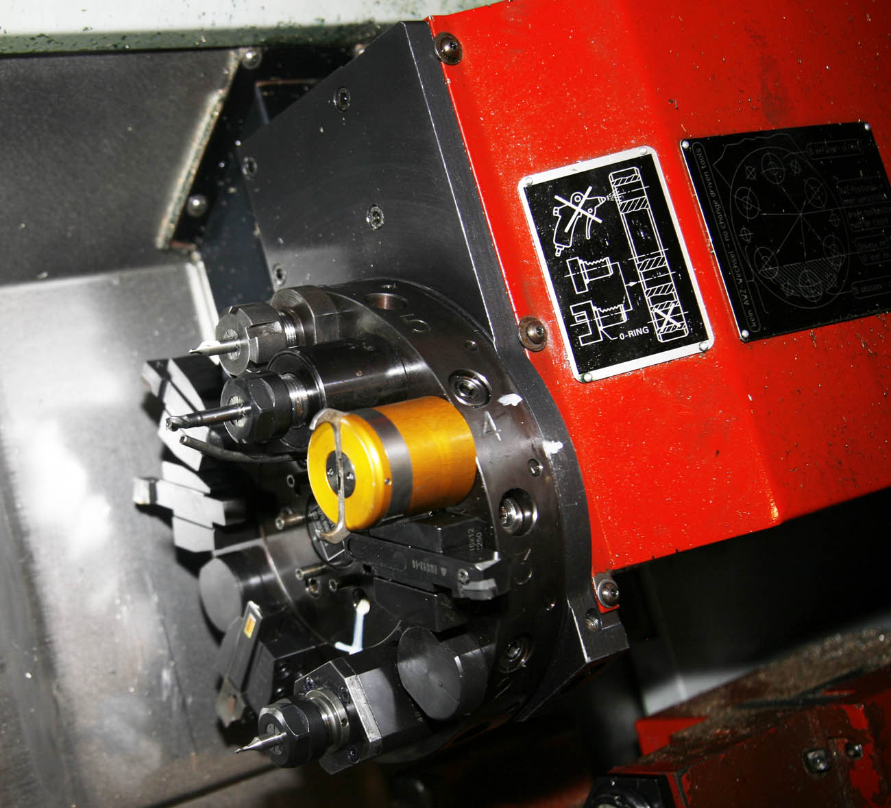
What makes the Emco so useful is that it has a rotating Sauter 12 - station head, and 6 of these toolstations are 'Driven', i.e. they have a seperate motor feed for driving milling tools (referred to as Live Tooling) - unusual for such a small Footprint CNC lathe.
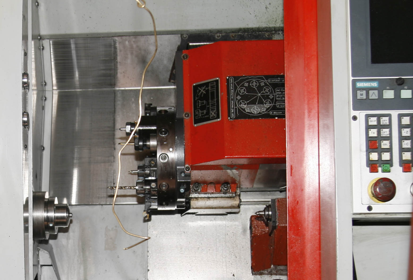
Below is an example of one of the driven tools I have for this machine - this one being a '90 Degree' VDI16 mill head - a small jewel of a tool.
By the way - the orange coloured tool above is a pneumatically powered 'Bar Puller', as with limited workshop space, I dont have room for a 3m 'Bar Feeder' alongside the machine. The jaws on that pretty little tool are quite capable of removing any digit silly enough to get in the way!
Collisions and Consequences
An almost inevitable consequence of running CNC machines - is that unless you are some kind of CNC magician (or maybe i am just crap!) - at some point you are likely to put in the wrong code or offset - forget to test run at slow speed - and have some form of collision - normally the tool and toolhead coming into fast and immovable contact with the spindle head or backwall.
In the last 6 years of running this machine, I have had a few - but 'Touchwood', most have been relatively minor - normally just resulting in a smashed tool (although still expensive with some Thru-Coolant drills running to £140 a piece!).
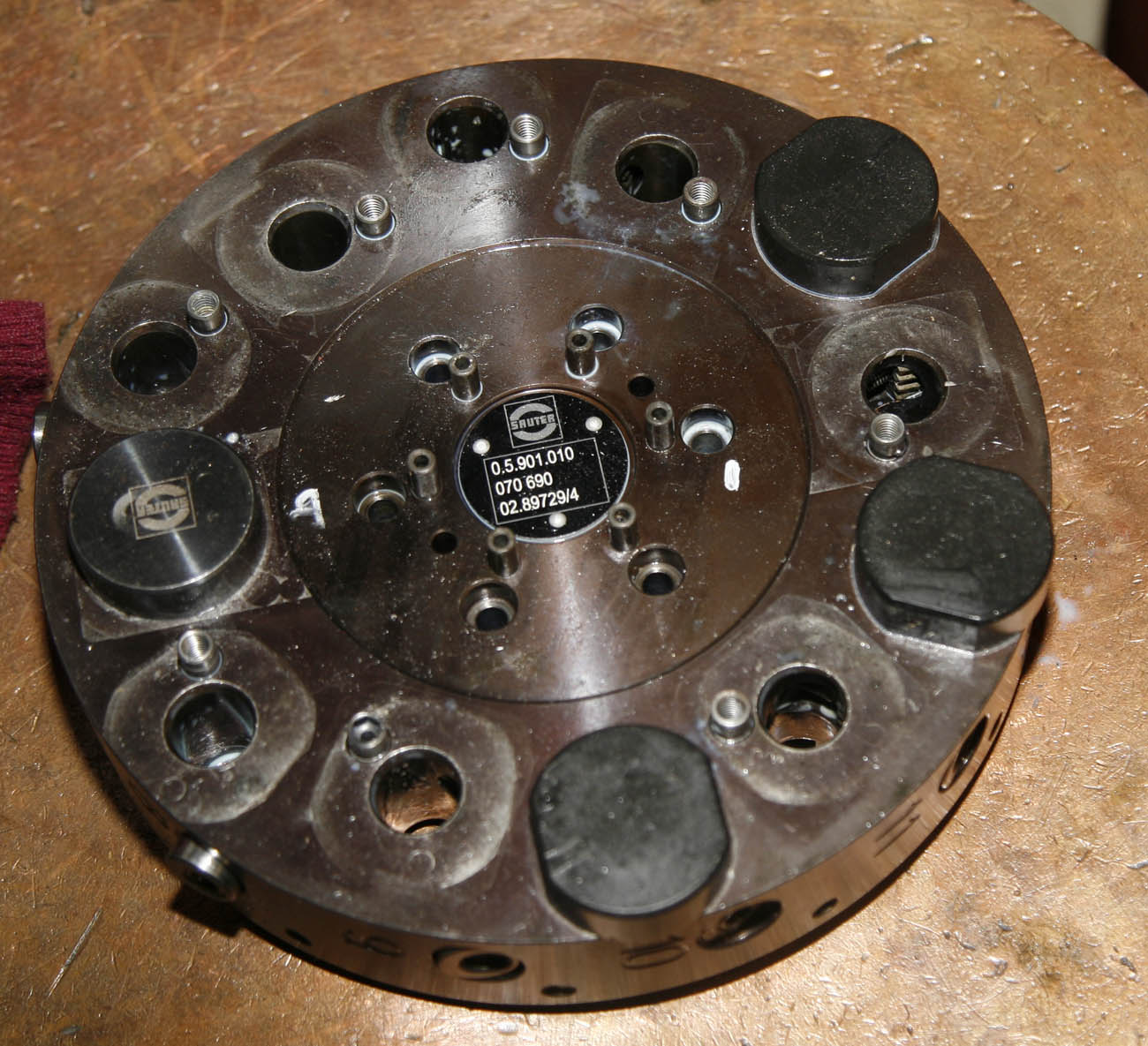
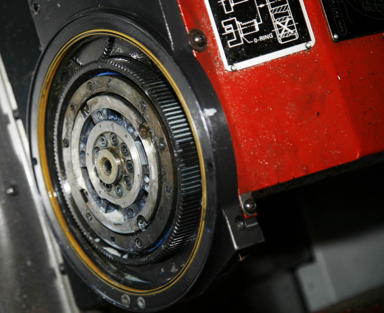
But one of the consequences of having a collision on this machine (and many other similar machines) - is that it can knock the toolhead off its 'Y' axis, i.e - you can never properly touch the centre pip when turning to the centre. This happened last summer . . . and with the help of advice from the UK Emco enginners - I found that the Sauter 12 station head you see here was capable of being adjusted fractionally along its Y plane, by loosening the centre spiral bolts - and tapping the head back and forth along its spiral - while using a dial gauge clock mounted in the master spindle - until the centre line is back adjusted. At least I know now how to do this for the future.
In the photograph below, i had removed the tool holding head, to ensure the spiral sliders were actaully sliding ok, as the head had not been stripped since I had owned it - what I found was a beautifully made - but dauntingly complex piece of machinery. the main drive gear for the Live Mill is just visible
2016 Onwards
Since that time a lot of water has gone under the bridge and I have learnt an awful lot about how to program CNC lathes . . . not only the actual G-Code language and fundamentals of CNC programming, but also all the clever little tricks you learn wtih any piece of specialist machinery, and some of the more subtle tricks on how to get the best finish or avoid 2nd ops if at all possible.
Note - for many CNC lathes an important feature is to have some form of mechanism that allows a bar of steel to be continually fed through the centre of the main spindle . . .where it is machined then gets parted off, and then the next length of material to be pushed through. By doing this - a real level of automation is possible, particularly if the lathe has the flexibility of a multi-tool head. In olden days ... when Norton were still at Bracebridge Street, the closest thing to this was a 'Capstan' type lathe, where a lathe operatior could perform about 4 to 6 operations, before parting off and the bar was pushed through, but these still relied on an engineer turning a lever between tools - I do know a couple of companies that stll use these pre-CNC Capstans.
Most commercial steel bar these days is supplied in 3 metre lengths - and a machine like mine would normally have a Bar Feeder attached to it - allowing a number of 3m bars to be fed in for high volume work.
In my case, space prevents a bar feeder, but I donated one of the 12 tootstations for a very trick pneumatic powered Bar Puller. This means a shoter length of bar could be fed into the machine, and after parting off - the bar puller would grab the bar, the collet would open, the tool head pulls back to a specifc point - pulling the bar through to the correct point, and then starts the next cycle.
Going back to the term '2nd Op' - obviously if this is required for a part to be made - as a large percentage of parts do, it means that once the First (automated) op is complete - the workpiece would then require manually mounting again for a further operation - i.e. something on the rear face being most common - requiring the operator to load every part indiividually for that 2nd op - far more time consuming and costly..
Over the 6 years of owning the machine, I have probably made about 200 different parts on the machine and written somewhere around 400 programs and subroutines - and the ones that give most satisfaction, is when I can figure out how to avoid that 2nd or 3rd op!
.
But What About The Maintenance and Upkeep of the CNC?
Well, through the last 6 years I have used the machine constantly, but maybe not to the extent that a 'normal' engineering company might be using it - i.e., being a one-man band, I have lots of other jobs to do as well - while many machines such as this will have a dedicated operator running it 8 hours a day. But that said I do use the machine constantly - and after 5+ years of extensive use, am not surprised a few things have gone wrong with it in recent times.
I have always made sure I check the oil, coolant and lubricant levels - particularly I expect the coolant level to need replenishing regularly - as evaporation and coolant locked in swarf quickly run it below minimum levels - and the first sign of this is that the Bar Puller stops working.
If I don’t pick up on this - and allow the level to drop further, to a point where each tool is not being supplied by a high pressure supply of milky substance (I use Castrol Alusol SL51, which is a water soluble coolant oil, diluted at about 7% with tapwater) - I soon get punished for not paying attention - because I find that carbide inserts are all glowing red hot - and any HSS tools I may be using are left with tips a molten blob! - that is the importance on constant coolant (suds) on a high speed CNC machine.
As far as issues in that time are concerned – well, I have had problems with the parts bin not opening and closing properly – which is controlled by a pneumatic cylinder (most of the pneumatics were manufactured by Festo, and like everything else on the machine – lovely quality) – where sensors are positioned on the cylinder to say when fully opened or closed. In the early days this was made a more frustrating issue, simply because there was no easy access to the cylinder, which could only be accessed by pulling out the parts capture drawer and trying to look up through the gap with a mirror.
As with any machine, there are lots of smaller issues in use – and although some are annoying, most you either eventually fix or work around. But about 3 years ago a more serious issue occurred in that the C-Drive stopped functioning correctly (the motor control that engages with the master spindle would not engage properly). This eventually entailed having to remove the entire top of the machine on the left to get access. Identifying the issue proved to be very difficult – and even trying to determine if the issue was electrical, mechanical or pneumatic was a challenge. At one point I had the electrical panels at the back of the machine ajar, so I could place a remote camera to my laptop – with the camera pointing at one of the Masterboards – so that I could run a test program, and see the coloured diodes on the masterboard light up to indicate it had received a ‘Signal In’ and another light up to show a ‘Signal Out’, while also watching the large Festo pneumatic master valve board – which had similar lights – and then following that through to the piston that moved the C-drive motor into place, and triggered switch indicators monitoring the movement!
It took a couple of weeks to eventually get to the bottom of the problem and fix it – luckily it turned out not to be a Masterboard failure as I first suspected – but the amount of time it took to diagnose and fix probably took 5 years of my life – and there were numerous times I felt like just giving up and calling in an Emco engineer (not easy, as access is limited around the machine and they are about 200 miles away from me).
As an amusing footnote to this failure – in the course of identifying the fault – and needing quick access to the pneumatics around the Master Spindle (I had had to remove all the main covers – which is a nightmare in my confined workshop) – I was talking to an Emco engineer, who told me the last versions of my model actually had an inspection hatch put into the main cover for exactly this reason. As you might guess – the next week I was out there with an angle grinder and hinges – and now my machine has a similar – if more Heath Robinson inspection hatch in just the same area! . . . and of course, access to the Parts Bin pneumatic cylinder is now a doddle as well!
Current Issues – 3 In a row:
So, the current issues with this CNC started in late Summer 2022. First of all, I noticed that when milling, a strange error message would appear when engaging the milling motor, which stopped the program, but only after about an hour or two of the machine running. My friendly Emco engineers had no memory of that problem occurring before – but it indicated the mill motor was struggling to maintain the correct feed/speedrate . . . reason unknown!
As I was not using the milling function much at the time, I let that issue ride, although I noticed when I was using the function, the time between failures was dropping.
Previous C-Axis Issues
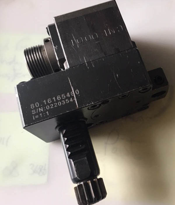
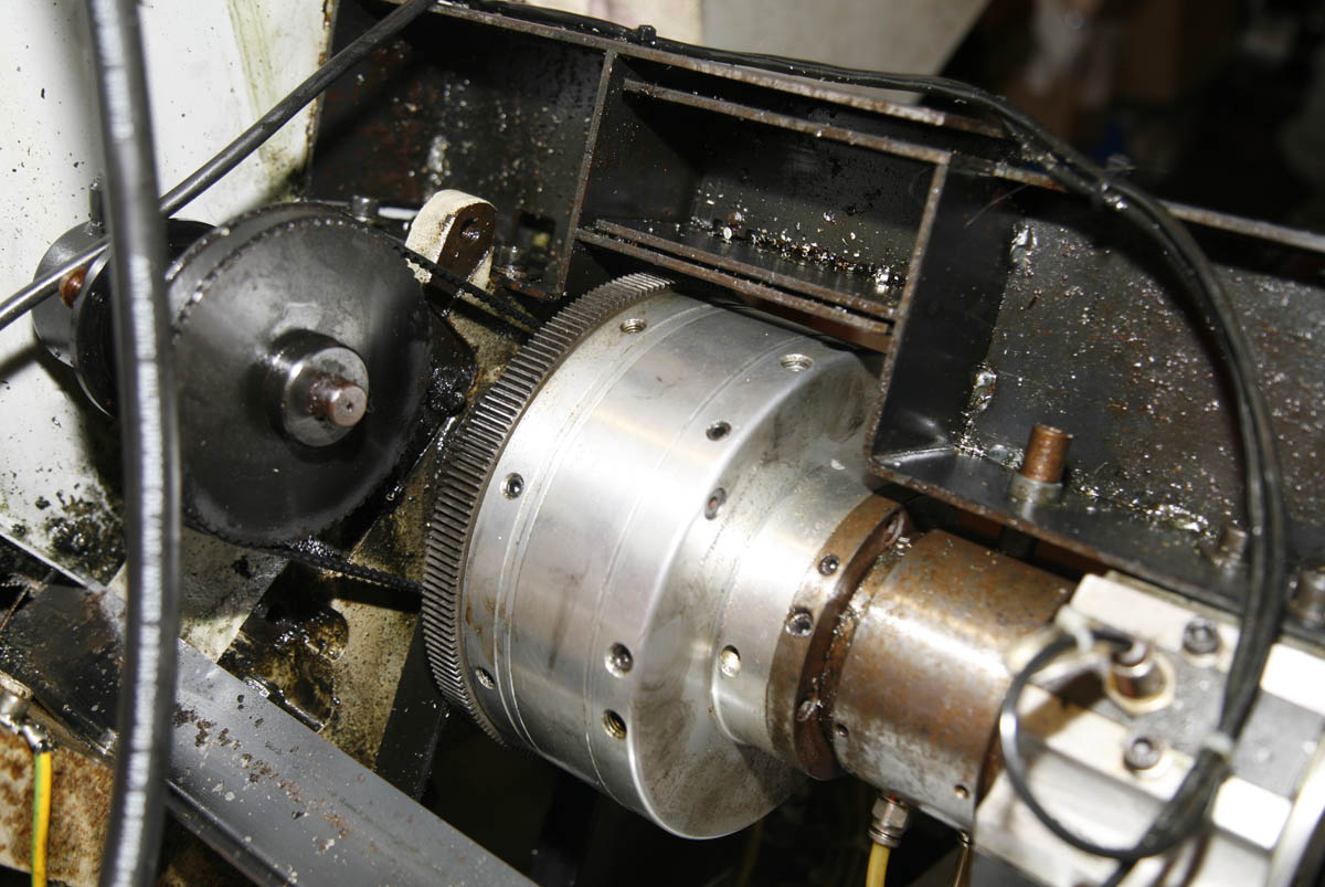
Not particularly easy to see - but a year ago (Summer 2021) I had another issue that took a lot of head scratching - my C-Axis had stopped engaging its secondary motor correctly - to rotate the main spindle, when carrying out ''Polar Interpolational' milling - i.e. milling a 'Hex' head on round bar.
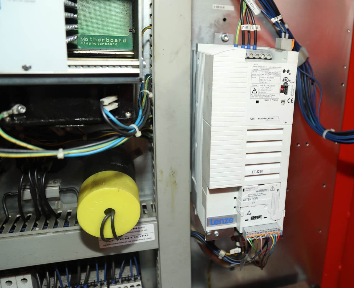
It does this by engaging a seperate motor - shown in the top left in the photo above, which will slowly rotate the lathe main spindle (i.e. the big aluminium looking shaft, with a belt gear in the centre)
So - by using a special 'Hex' program, where I just input the feed rate and size of Hex I require - the main spindle will slowly rotate, while a 'parrallel' Live milling tool is spinning in one of the Sauter tool positions, and at the same time moving up and down on the C-Axis in sync with the rotating main spindle - creating a hex profile on the round bar. Very 'trick' to watch - but also very difficult to figure out how to fix when it goes wrong! . . .Once all the main CNC covers had been removed (not easy in my small workshop) It took a number of days, and much poring over wirting diagrams to finally figure out the issue and fix it. And as always, I was very grateful for the email support and guidance from the Emco guys themselves.
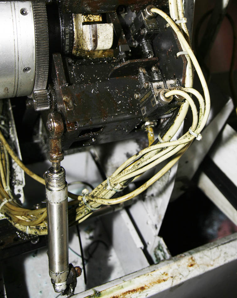
Difficult to make out below (beneath all the residue oil and gunk of many years of use - under covers), but but here is the engagement plate and 'sender switchs' for engagement of the C-drive rotation motor. In the lower corner is a Festo pneumatic cylinder to power the engagement and the harness are a combination of sender and sensor wires and pneumatic tubes - it took a while to work all that lot out!!
Current Issues - How It Started in Autumn 2022 :
The current spate of CNC issues started in September 2022, when the compressor that provides air for the CNC pneumatics went Poo-Tong.
The Emco has quite a big demand for air - as it has multiple pneumatics, most notable being the 5c collet or Rohm chuck requirement - as
these are pneumatically controlled.
Due to my workshops not being on an industrial estate, I like my CNC to be as quiet as possible, so a 'quiet compressor' is a must.
I would love a Hydrovane screw type t'quiet' compressor
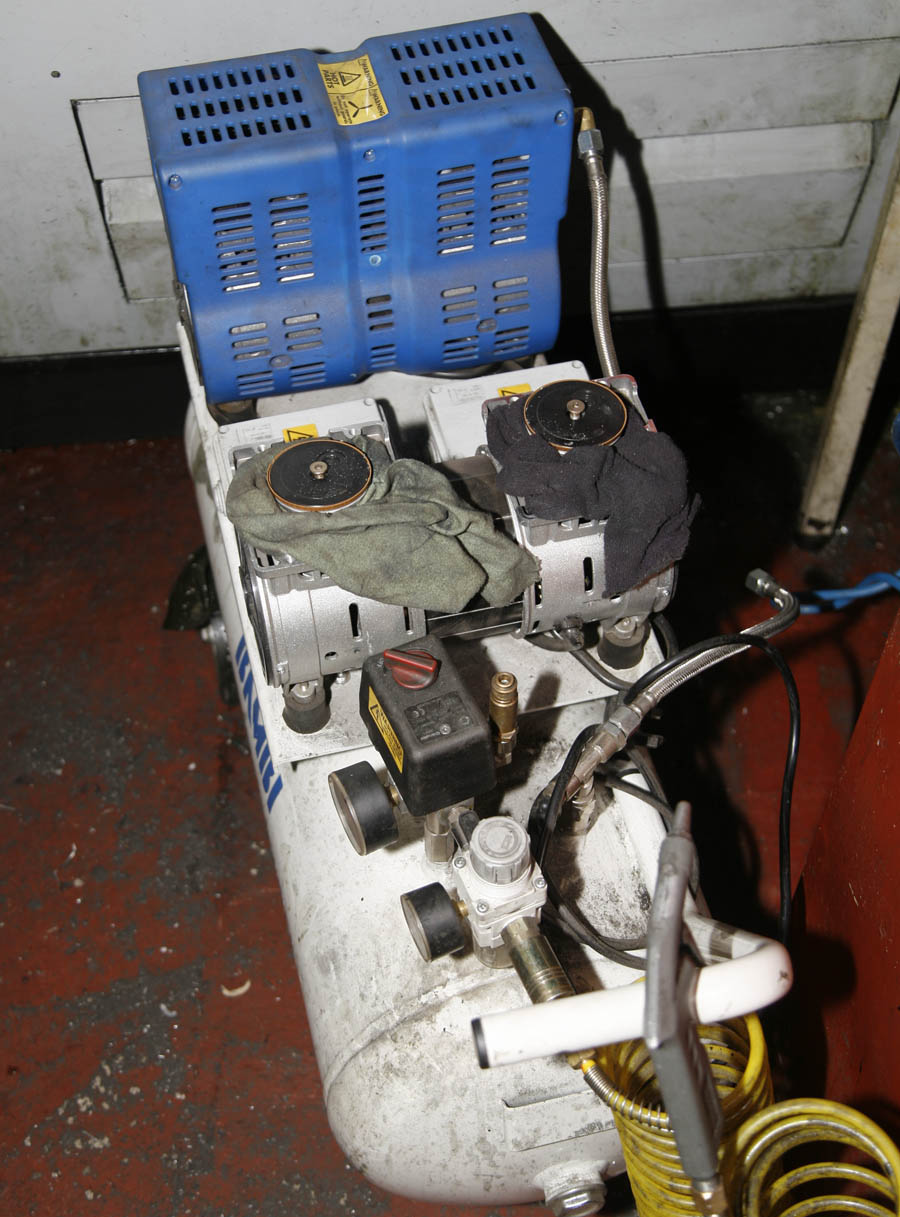
but as well as being more money than I can afford . . . the smallest Hydrovane available is just a bit too large for my available space. Instead, since 2016 I have been using these very good value Bambi 4 cylinder 'Ultra Quiet' compressors. They are well made and great value - but only have an (approx) 65% Duty Cycle - and that is just a little bit less than the Emco requires, hence since 2016, I have had to service the motors regularly and change liners, seals etc - as the motors run dry.
However, in this case - in September 2022, although the compressor was still producting air, I could tell it was very sick, and eventually a rather terminal 'bang' one afternoon, necessated the stripdown shown here - to reveal that one othe twin cylinder motors had actually thrown a connecting rod. Although it cannot be seen in the photograph . . . part of the rod was actually protruding through the crankcase! Normally I would be searrching on E-Bay for a similar compressor - and rob the motor off it, but as we had some rather difficult family issues (with my mother being ill) going on at the time - eventually it was easier to just buy a complete identical replacement compressor - delivered and fitted within a couple of weeks - but bank balance poorer!
But then in September 2022, came the first of the expensive failures – when the ‘Quiet’ compressor I have dedicated for this machine started to sound a bit rough. I use Bambi PT50 4 cylinder compressors – mainly because I don’t have enough room for a Hydrovane. These compressors are well put together, and excellent value for money – but are probably not designed for the heavy duty cycles they get when I use them (as well as the enclosed space they sit in – with little fresh air). Because they run ‘dry’ (i.e. no oil in the motors), I have come to expect they wear out the piston seals and liners in time, and have replaced these numerous times. In this case though – one of the motors sounding a bit rough – very quickly changed to that same motor giving a loud and terminal ‘Bang’. On stripdown, and removal of cylinder head and barrel liner, it quickly became clear what the issue was . . . it had thrown a con-rod, part of which had tried to exit through the crankcase wall!
Unfortunately, at around the same time – we had some serious family health issues which were more important for me to deal with, and rather than looking for a new motor for the same compressor (or investigating a Hydrovane again), eventually – I just went out and bought a complete new Bambi on Ebay . . . delivered two days later, installed and CNC back running again the next day! Not the cheapest ‘fix’, but quick, easy, and I know what to expect from the new one – and that it will do the job.
. . . Then a More Serious Issue Occurred . . .
Fast forward then to Xmas period, and although I had been able to do some CNC work, the family issues had meant I had taken time away, and the machine had less use. But in the two weeks leading up to Christmas we had had a particularly cold spell – well below freezing, but followed then by a complete change – it becoming mild and damp. I noticed at the time the change was quiet extreme because all the tooling in the workshop the Emco was in was soaking wet (despite most being sprayed in Duck oil). My main workshop is very is very dry normally, so I was surprised at the time how extreme this change was.
This change coincided with Xmas break, and although I had only had about 3 or 4 days of the machine being down – I knew in the period between Xmas and New Year, I had a batch of parts to make. So, about 3 days after Xmas, I went out into the workshop and fired the machine up as normal. The startup process progressed much as always did, with the Emco PC computer (at the back of the machine in its own cubicle above the main electrical panels) going through its startup routine, and the sound of the compressor pumping away to full pressure alongside that.
I confess I was not really paying attention to this going on, as I was already looking at the setup tools for the job I was about to do . . . but after a minute or two, a small flashing alarm started to go off subconsciously in the back of my head! After a few moments, this reached a level of Defcon2 – and it shouted at my conscious side to Pay Attention! . . . . there was a definite smell of burning coming from somewhere.
At this point the powering on process had completed and the Emco Win NT operating system was showing on the CNC screen, but something seemed amiss – and then I noticed what looked to be smoke in the Working area, i.e. where the toolhead was, it was only faint – but definitely there, and definitely smelling very electrical!
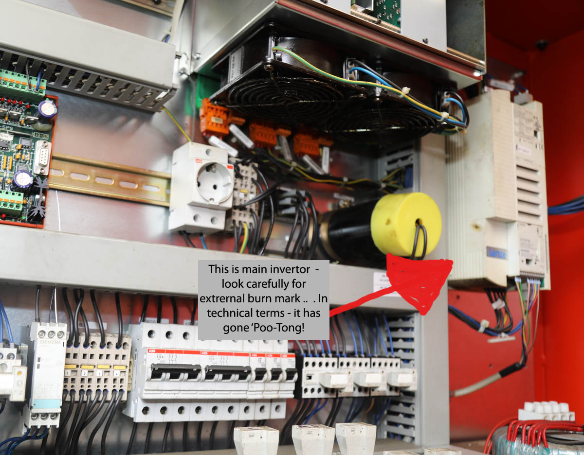
Then The More Serous Issues Occurred! - Main Invertor Failure
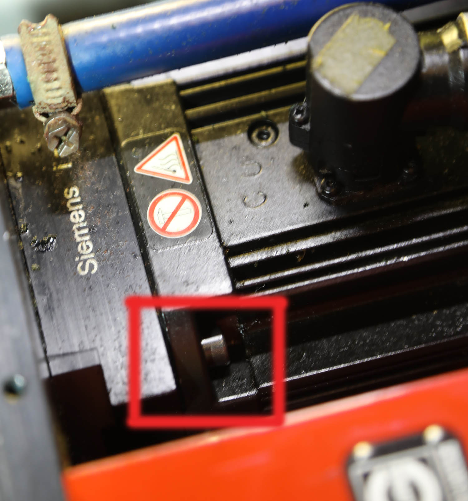
See text at the side for the narrative behind what happened here . . . but the photo above shows the back of the Emco with the covers removed (click on thumbnail for larger version). .. a bit more complex than the electrics for the 1950's Smart and Brown lathe that sits next to it!
A nasty smell and smoke coming through into the machining area at the front indicated that something pretty serous was wrong in here. The first two weeks of January were spent trying to highlight the issue - before a loud bang and sparks from the area ringed in red told us for sure it was the main 3-Phase Lenze Invertor had blown - a major component of this model - and definitely one of the individually most expensive!
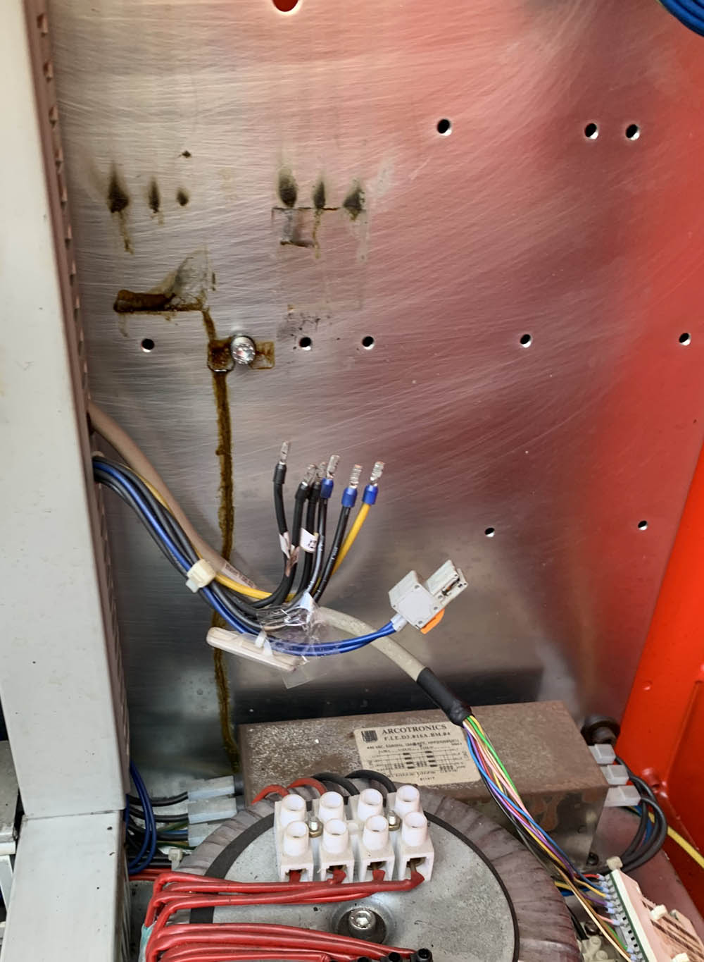
In the photo below you can see the stainless steel backwall, once the invertor had been removed - with traces of electrical burning just visible .
By the way - at the bottom of the photograph is one of the biggest transformers I have seen - dont want to be touching that when sniffing around looking for faults with the power on!
Not surprisingly, I dident mess about – I shut down the machine and compressor immediately, and immediately went for the fire extinguisher I keep on the wall next to the machine. With space and access around the machine being limited – I spent the next hour trying to remove panels and get access with a torch (and fire extinguisher) – and had figured the smoke had seemed to come from somewhere in the back of the machine – the main electrical area.
Obviously, I did not try and go any further on the day, but the next week was spent removing panels and making sure I had access both front and rear, so that – with a friend I could run it again to see if the issue re-occurred. After a further attempt – which then seemed to indicate the PC was at fault (removing the PC and running it up and testing it off the machine proved this was not the case) – on the 3rd attempt – we got a conclusive answer, after 5 minutes of powering up – with myself at the operator console and a friend at the back of the machine (a safe distance from the electrical doors!), with fire extinguisher in hand, there was a loud bang – and my friend reported seeing a large streak of blue sparks come out from a box in the corner of the electrics . . . . Bugger!!
As per the photos you see here at the side – this turned out to be the terminal expiry of the main 3-Phase Invertor module . . . as it turned out a rather expensive and difficult component to replace! It was a large Lenze programmable high amperage unit, and not only would it turn out to cost the price of a nice mid 50’s OHV Norton to replace new, but it would also need programming by Emco in Austria specifically for my machine – Agghhh!
At this point, probably early January by this time – having spent most of New Year period doing investigation and stripping, I had a particularly good piece of luck – while talking to one of the two UK Emco engineers I know well, he mentioned he thought they may have a good second hand Lenze unit from a machine they scrapped a while ago, on checking – not only was it the correct unit (there are lots of Lenze inverters that look similar, but mine seems to be a particularly uncommon variant) – but this one had a sticker on its box saying ‘325-II’, meaning it had the correct programming for my machine, fantastic. My UK Emco sales contact had to check with the parent Austrian office for a price – but after a little bit of friendly negotiation – I was able to purchase the inverter for just the price of a nice 1930’s OHV engine . . . better than the intimal ‘full bike’ option.
Lenze 3-Phase Invertors
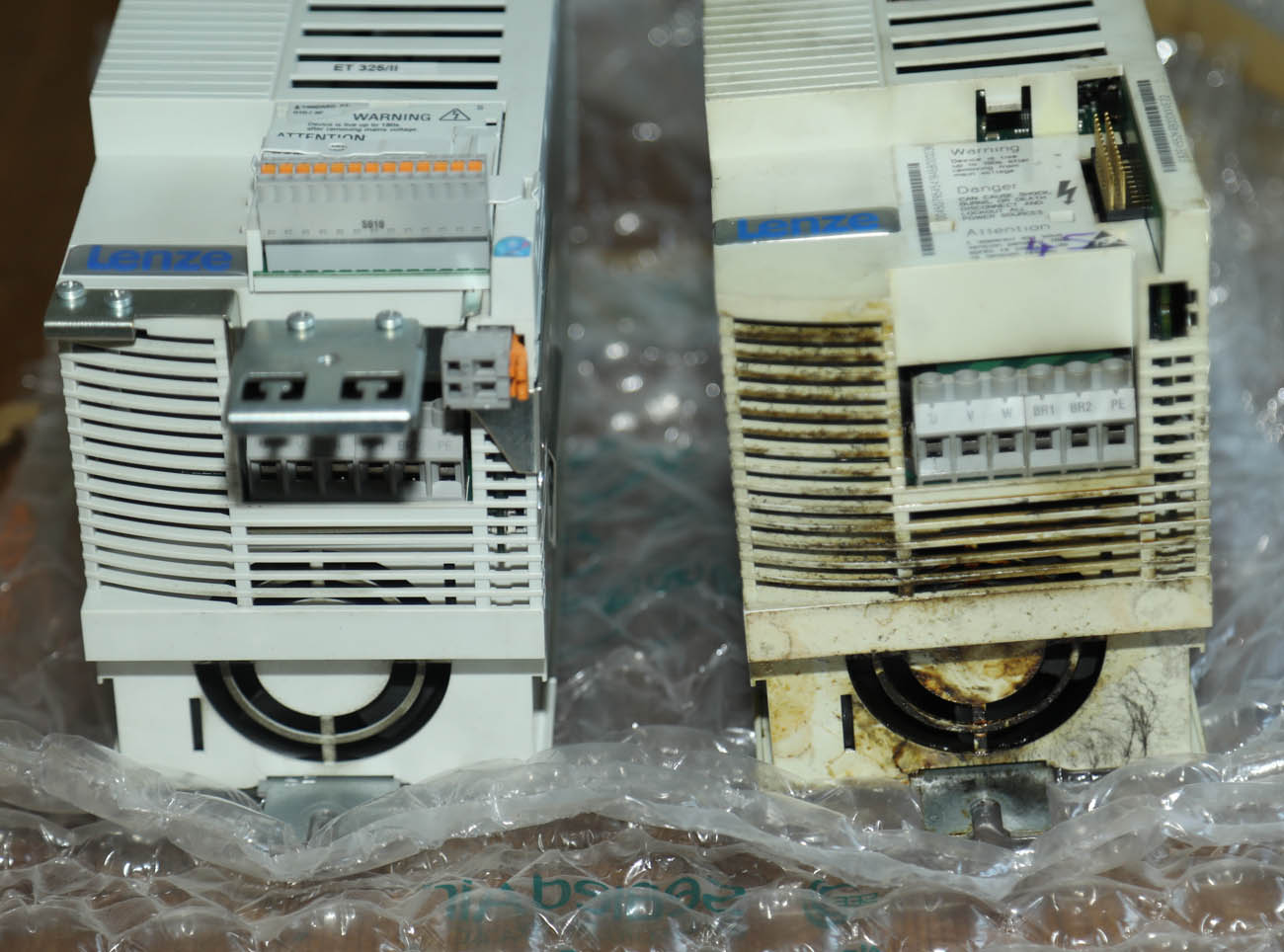
Top photograph on the right shows the original Lenze 3-invertor after removal. As well as clearly showing signs of having gone bang - it also gave out the most awful smell of biurning wiring and oil. Talking to a good friend and CNC machinist of many years, he conferred on what I think was the cause - many years of faint coolant mist seeming through the sealant into the electrical compartment and 'gumming up' the invertor fan and panels.
These invertors are quite special and very expensive - having hunted around I can see they come in all voltags and power flavours . . . but this is quite a rare size. More than that - they have to be programmed to the machine they are to be fitted to. I was extremely fortunate that Emco UK themselves came to the rescue - and were able to supply the one on the left of the photo - looking almost new, and already programmed for my model - it had come from a machine they had recently scrapped . . . and their only one left!
Below shows it fitted - small wiring at front turned out to be very important
You can see in the accompanying photos, when comparing the original (burnt out) inverter to the very clean replacement unit from Emco (which actually looked totally unused) – how different they looked in condition – but having closely inspected the old unit – that smelt awful by the way, I think I have an idea what the cause of the problem may have been - found that all around the fan at the base of the unit was a horrible gummy oil like substance. I think that maybe over the last few years of continuous use – inevitably a small amount of coolant mist may have got into the rear electrical section of the housing – which is all sealed off from the main working area, and this coolant had eventually been sucked through the fans. Maybe the sharp change from freezing cold, to heavy condensation on everything in the workshop had caused some of this oil/coolant residue to drip into the electrical circuits of invertor, or just totally gummed up the internal fan?
Regardless – having now had the CNC machine inoperable for about 3 or 4 weeks I was keen to get the replacement inverter fitted and make sure everything was ok – and no further damage had been done when it went bang.
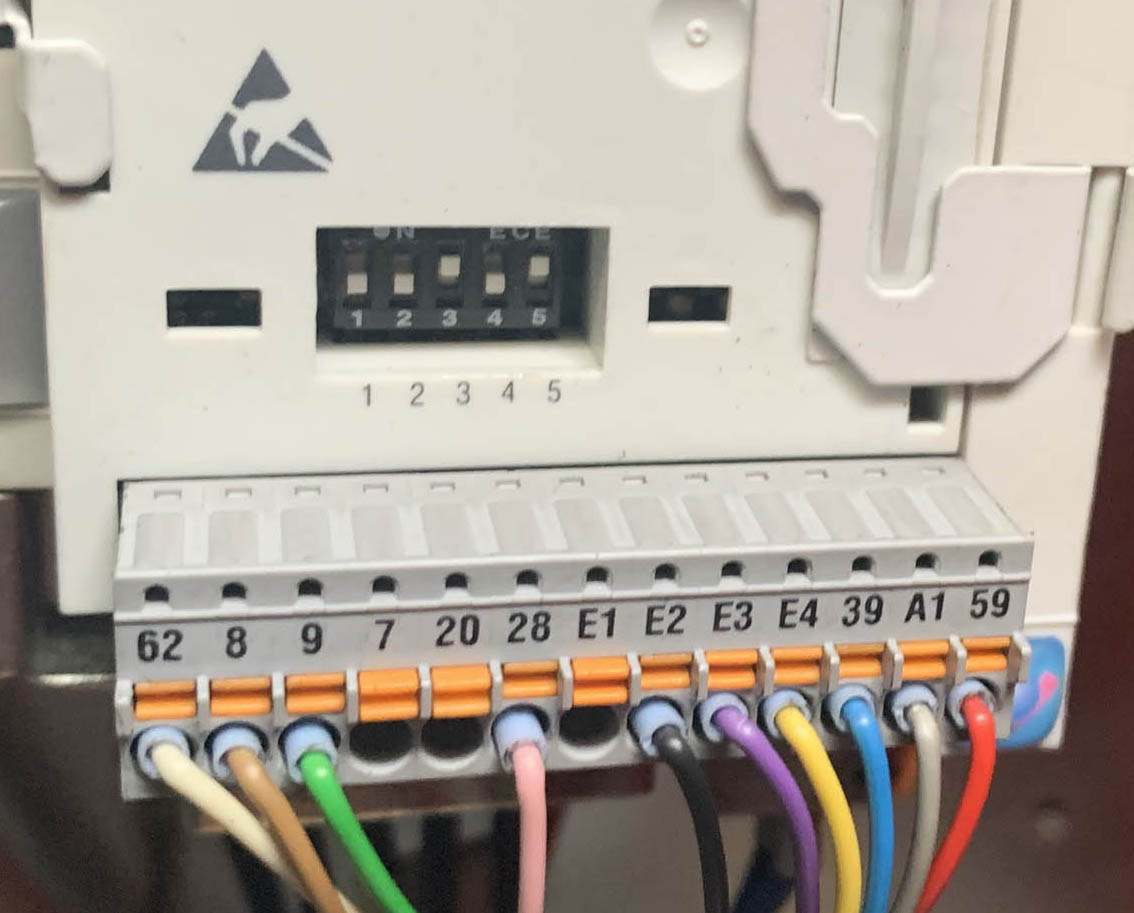
A Slight Error of Judgement With the Re-Wiring!
But just when things were looking a bit more positive, I have to admit I cocked up a bit! When re-fitting the invertor the next day – I had very carefully fitted all the main power connections to the main invertor. However, I also had to carefully unscrew every one of the many smaller wires that were fitted into a separate ‘plug-in’ connector at the front of the invertor. I think this plug in connector controlled the programming of the invertor, and the replacement unit was a slightly updated version of my old one, with a slightly different plug in connector – so I had to carefully remove every wire, and screw it into the corresponding connector on the new unit.
So it was with some trepidation (and of course a friend at the back of the machine, with fire extinguisher again), that I powered up the CNC and waited for everything to load. After 5 minutes everything had loaded as normal and the operating system went through its normal start up and referencing procedure. I fitted a piece of bar into the pneumatic collet and then ran a test program. Initially all looked ok, and the X and Z axis quick traversed the tool head as normal. But then the main spindle started . . . and a screaming noised emanated from down where the main motor sat and I watched the collet started spinning at a rate that seemed far more than the 2000 RPM it was supposed to be spinning at. a rate that seemed far more than the 2000 RPM it was supposed to be spinning at. I Immediately stopped the program, looked all around the machine to ensure all else ok – before nervously starting the program again . . . but exactly the same thing and this time even scarier – the main spindle ran for a few seconds at what was quite clearly a speed far in excess of 2000 RPM, before the operating system cried enough and the CNC shut itself down – bollocks again!
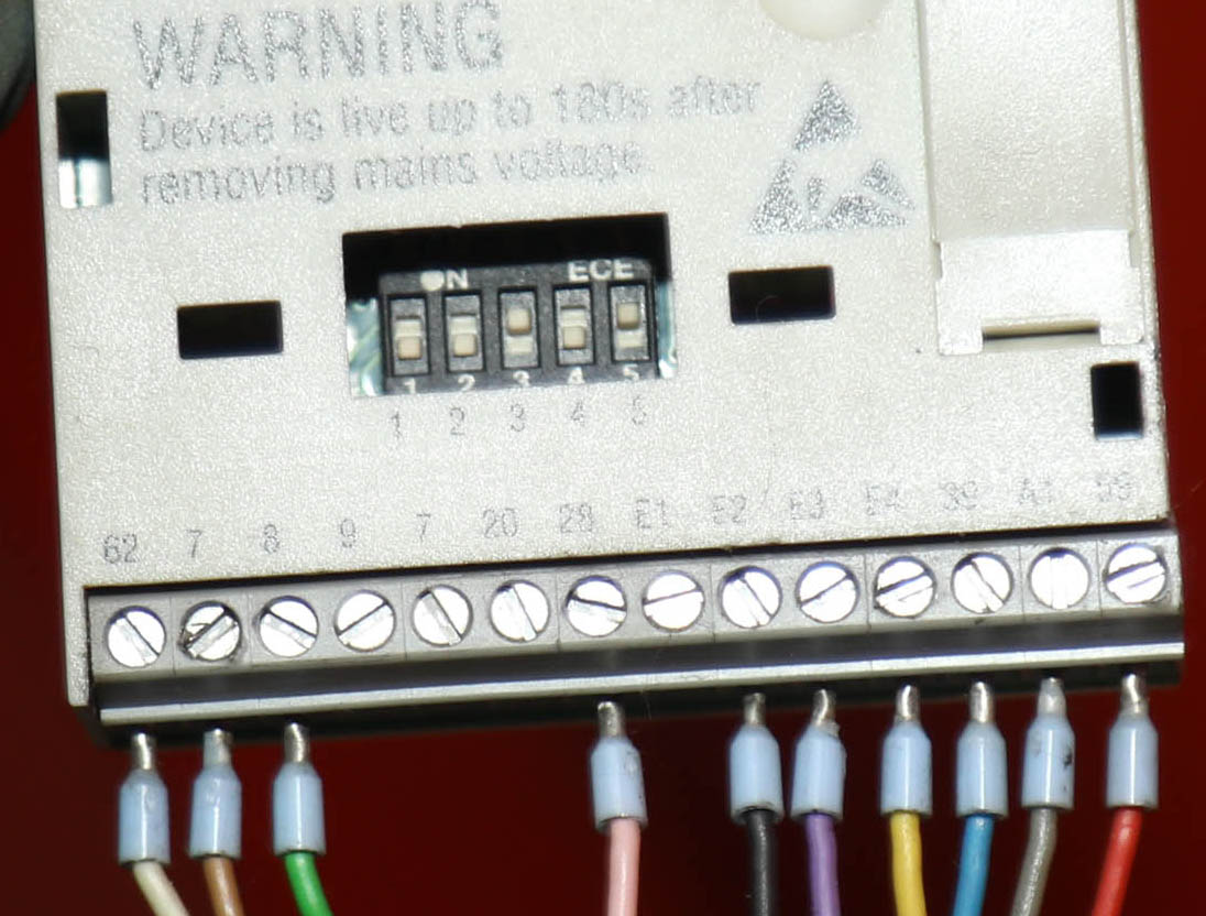
Spot The Differnce - Almost a Very Expensive Mistake!
The new invertor, when it arrived, looked almost identical to the old unit - but was a slighly younger unit than my burnt out original. Shown above is the Plug-In programmable unit connector, while the photo below shows the new unit - can you spot the difference? Unfortunately when wiring up the new Plug-In connector down in the badly lit guts of the electrical cabinet - I unscrewed the wires from the left,, and replicated them - and then did the same with the wires from the right. Unfortuntely . . . I did not notice that on the updated connector, for some reason they had decided to omit the duplicate '7' connector.
I was very fortunate that when I started the lathe up - the main 3-phase motor did not jump out of the machine and grab me by the throat- it was running so fast!
My cockup - I need to use a torch and get better glasses!!!
I Immediately stopped the program, looked all around the machine to ensure all else ok – before nervously starting the program again . . . but exactly the same thing and this time even scarier – the main spindle ran for a few seconds at what was quite clearly a speed far in excess of 2000 RPM, before the operating system cried enough and the CNC shut itself down – bollocks again!
Get a Better Set of Glasses!
By this time I had had about enough of being a CNC owner – and amateur CNC mechanic, and frankly was ready to go back to manual lathes – the stress of so many issues, and scary costs was getting to me – but I knew I had to persevere, so ended up taking photographs of the wiring blocks . . . so I could make sure the programming on the later invertor was the same as mine – I sent the photos off to Emco and awaited a response.
As it turned out, I got a reply from the Emco engineer the next morning – saying that Emco Austria had confirmed the two units had exactly the same programming – and should be totally interchangeable – So all I could do was sit and look despondently at the photograph I took of the Plug-In unit of the old unit (that I had taken before removing the wires), and the picture of the new plug-unit, with the same wires now screwed into that plug-in . . . all the wire colours being in the same order – so what had gone wrong?????
It was then, after looking between the two photos for about 5 minutes I noticed a slight anomaly – although all the wires were in an identical order from left to right, the new plug in connector seemed to have a slight difference – there was additional empty wire socket in the centre! . . . and then I suddenly realised what the issue was, looking closely and reading the tiny plastic numbers moulded into the connector – it turns out that the replacement plug in socket had been amended, and it had had a wire connector removed somewhere in the middle (which actually was for a duplicate number on the earlier connector). In the murk of the guts of the machine, when I had been wiring in the amended connector the previous day – I had worked from left to the middle, and then from right to the middle . . . and although both were in the correct order – because the number of connectors was now different, two wires in the middle had become transposed, buggerr!!
Although worried I might have done the main motor some damage, or worse, I corrected the wiring – and was more than a little relieved and pleased, that on re-trying the test program, this time the main spindle behaved impeccably, and normality had been restored!
So that about wrapped it up for that issue – I don’t mind admitting, the month of January had pretty much stressed me out – watching your main machine go up in smoke is never good for your ticker, and made worse when you have no idea what is wrong, and when you find out – realise you might need to re-mortgage to fix it . . . but at the end, I feel very fortunate that Emco had a spare unit on their shelf, and grateful they were so helpful. I was also reasonably pleased to have (finally) made the fix myself again, although if I was not such a skinflint I would have dearly loved to hand the task to a professional CNC engineer and let him have the stress– and of course while doing all of this, I was not making parts to sell!
And Finally . . . . Issue No 3 : Lenze Live Milling Motor Issues
Actually - of the 3 major issues, and two more minor ones I have had with this machine in the last 6 months – as I said earlier in the article, this one was the first to manifest itself . . . initially it only occurring occasionally, or after a prolonged period of machine running, but as time moved on last summer, it got to a point where any milling operation within a program would trigger the error message that stopped the program.
So, after a period of a few weeks of reliable running with the new Lenze invertor fitted – and a few non-milling urgent batch’s crossed off the ‘To Do’ list, I decided to bite the bullet and address the milling issue.
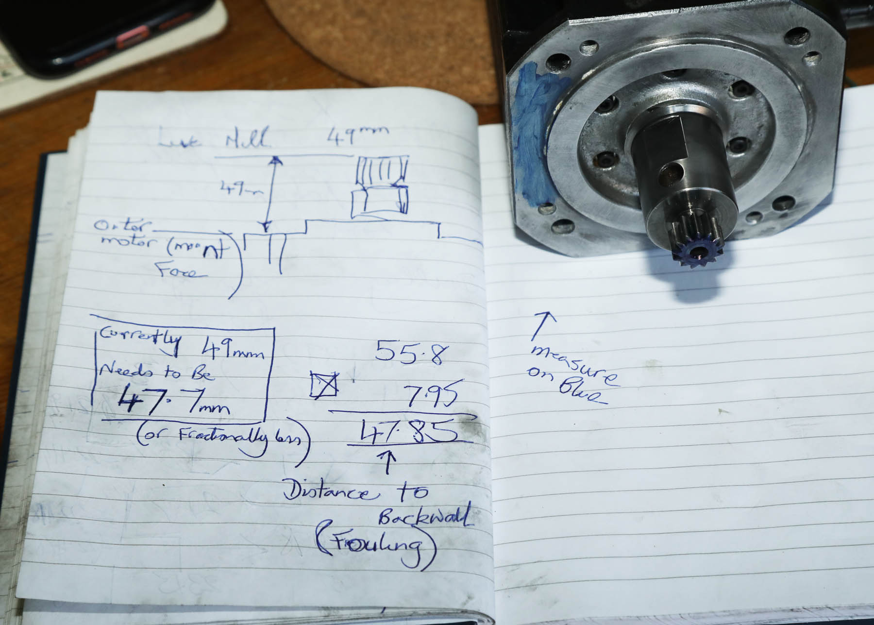
I had never stripped down the Emco X/Z Axis head before, and was more than a little nervous about the level of complexity I would find under the bright red cover (shown in the accompanying photos). So – just as I always do, before doing anything else I emailed my two favourite UK Emco engineers, to at least get a ‘Heads Up’ of what I would find. I had in my head that the milling motor would be relatively small – i.e. about 6 inches wide and deep and probably no more than that in length. I was told that it could be accessed from the main operator door without having to remove any of the large enclosing covers – but there was not a lot of room under the coves – and that the motor was mounted to the toolhead backplate by four screws – and that two of them would have limited access.
So, in late Feb/March time, with an increasingly growing list of Norton parts I needed to re-make, that required the milling head . . . I finally switched the machine off, and started to remove the tool head covers., having first cleaned the X/Z head down with light oil, to remove all swarf and gunge . . . as I knew I would be getting dirty sticking my head into the gubbins of the machine.
As expected, removing the covers was relatively straight forward, and having manhandled them into the swarf collecting area at the base of the machine – I could get a better look at the milling motor – which had been shoe-horned in (especially fore the 325-II originally I expect) and was tight up against the major casting of the 12 station Sauter machine head.
The Mill Motor Was Bigger Than I Expected
First impressions as I looked at the milling motor were twofold – firstly . . . agghh, it is a Lenze make motor, that means good quality – but expensive. And secondly, bloody hell, that is a bit longer than I expected! It turns out the milling motor is about 3” x 3” in height and diameter (BTW – my CNC is setup in metric ‘mm’, and all my Autoccad/Inventor drawings are in dual inch/mm dimensions, but I still like to quote imperial inches when I get the chance!) . . . but what surprised me, is that it was approximately a foot (12”) in length . . . a lot more substantial than I was expecting. And as I had been pre-warned, it had four allen head screws holding it to the main toolhead backwall – but only 2 were easily accessible. I was surprised by the amount of swarf and crud that had made it inside the big red cover . . . and had filled up every available space between the motor and the Sauer tool head – but after 10 minutes of washing down with degreaser and airgun, I was able to get at the allen keys to remove the motor. For the inaccessible rear screws – as my mates at Emco had recommended -I had made up a ¼” drive extension length with the correct hex socket – and had taped it together with Duck tape, so I dident end up with the socket head stuck somewhere at the back.
Before attempting to undo the mounting bolts I loosened and disconnected the two ominously large wiring connectors. I was expecting the first one – a large 3-phase power connector, but as I removed the second/rear connector – could see that it had far more pins within the connector than would normally be found on any ‘manual’ milling motor . . . more of which in a moment. As always with an older machine – my main worry was if I could not unlock the hex mounting screws – but the extension socket bar did the job – and by applying a mixture of care and grunt - all four hex screws released eventually and the motor was able to be pulled backwards from the mounting wall and removed.
And Then Finally - 'Live Mill l Issues and More Investiagation Required . . .
Photo above shows the main working compartment of the emco (with 5c collet on the left) and the 12 Station Sauter tool head - mounted on the large X/Z Axis Turret (in red). I knew that a milling motor also lurked under there somewhere - but admit to a sense of trepidation, as I had never had the cover off before.
After taking some very helpful advice from those kind folk at Emco UK, here is what I found underneath the covers. In the bottom half of the photo was the expected large and robust Sauter rotating head mechanism (I have a cutaway drawing in my Emco workshop manuals - it looks bloody complex inside that red box!). But above that I found the milling motor - admittedly substantially longer than I was expecting . . . and with two big connectors with lots of pins on them . . . . this was a bit more complex than I envisaged!
Clean It, Look At It - Then Pass It To Someone Thats Knows What To Do!
After washing it down with degreasant, I gave it as much of a check over as my limited knowledge would allow . . . but there were no obvious signs of issues – the motor span freely, the drive gear looked fine – as did the idler gear still mounted in the backwall, and there were no obvious signs of anything burnt out or damaged. All I could find of note was – the second wire connector – the one with all the pins, looked to have a bit of dampness inside the connector itself, despite it being fitted with a Neoprene O ring to protect it.
Not really knowing what else I could do myself, and knowing that the second connector probably meant it had lots of sensors inside – I decided I needed to pass it on to someone that at least had a clue of what they were doing with it!
To cut a long story (already) a bit shorter . . . by Googling any Lenze specialists in the Midlands area of the UK – I cane across a company in Northampton called Unis Group - see Link here: https://www.unisgroup.co.uk, and after talking to the salesperson, they told me they could pick up – at no cost at this stage, and then put it on test rig and provide a quote for any work that needed doing. Although sceptical at first – as I imagine that kind of service would be costly – they turned out to be true to their word, and after degreasing and carefully packing in a stout box, it was collected the next day by UPS, nice and simple. I also passed on for their engineer what information I had about the motor and the machine it came from
After a couple of days, I contacted them as we had agreed – Initially they could find no major issue, with the motor itself - other than one bearing having slight wear, but found the sensor panel inside was waterlogged. Unfortunately, it seems the whole CNC parts industry have been struggling post Covid in the last year and there is a shortage of spare parts. They were not sure they could easily get a replacement . . . and guess what – being a Lenze component from Germany, it was not likely to be cheap! Having talked to them again while waiting – they did actually try to dry the sensor panel out for me, but when they ran they tested it next day on their test rig – no joy, it was still giving erroneous information – and this looked to be the reason it was not working for me.
However, after a few days of waiting – and ringing to check on progress, my contact at Unis Group the good news, that they had now heard back the correct sensor was available – and provided a full quote for the part, fitting and testing and return of motor to me. This was not a cheap repair – Just over £1k with VAT and return, but not the end of the world . . . and as the repair came with a one year warranty, much cheaper than trying to buy a new motor of the correct type across Europe, and frankly far less stress!
Unfortunately, It would take about 6 weeks for the sensor to arrive and be fitted – so again, the machine was down for a considerable time with no parts being made, before being informed it was fixed – all working, and would be with me next day (after payment of course).
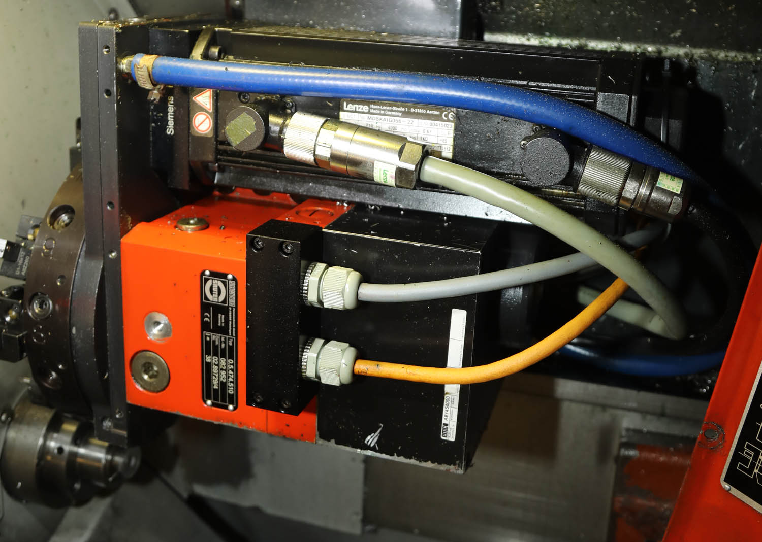
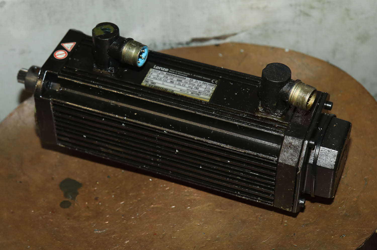
Removal of the Lenze Milling Motor - The Blind Leading The Blind . . .
The Lenze milling motor was secxured to the backwall of the tool turrent by 4 Metric Allen screws - the two at the front were easy enough, but the ones hidden at the back required a bit of fiddling and an extension to the 1/4" scoket shaft to get access to
And below is the milling motor removed and readyh to go off for diagnosis.
It is an impressive looking motor with both power and sensor inputs visible - it being a Lenze 3-phase MDSKAIG056 unit of 1.5KW and max 6000 RPM
Rebuilt Mill Motor - Ready To Go Back On - Once Gear Fully On
When the motor came back from fixing it had been fitted iwth a new sensor and plugin connector, and then been rebuilt. Unfortunately the gear arbor was not quite pressed bback on far enough - but that was quickly resoilved
And below - one of the first jobs back on the Emco CNC, once the milling motor had been retested and back operational - stainless steel -- Norton Clutch Spring Lipped Screws - where the hex has been milled - very pleasing to have got it fixed - as lots of jobs like this queued up to do
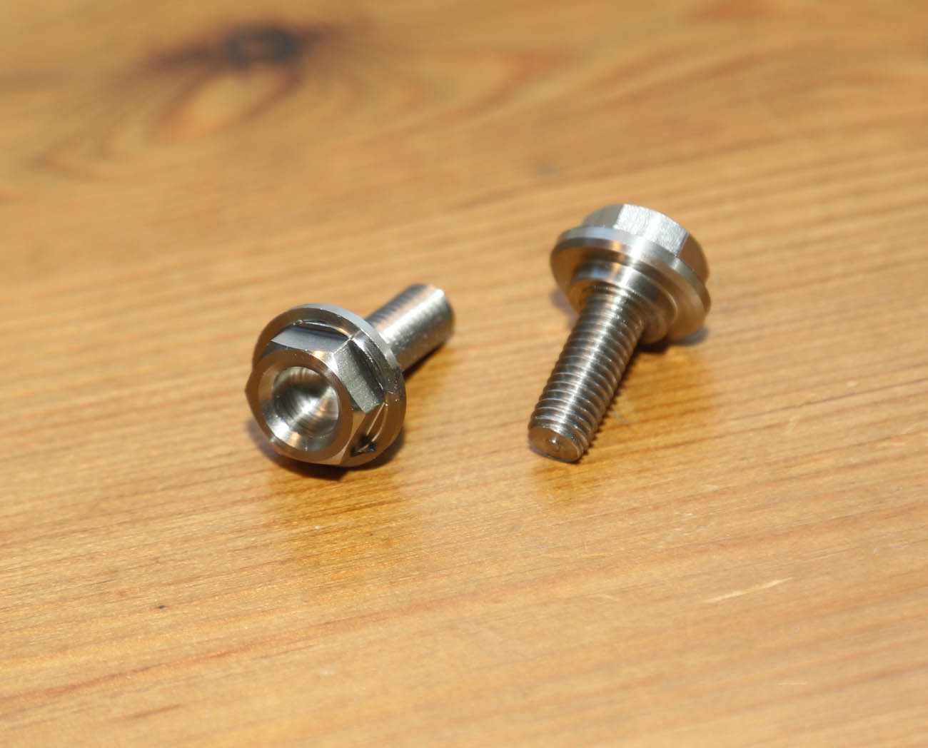
And when it did arrive next day – I was duly impressed just how clean and sparkly the motor was – looking virtually new, and with a new sensor connector fitted. Re-fitting tunred out not to be as straightforward as hoped – as the special drive gear and not been pressed on quite as far as it was originally – so was fouling the backwall of the toolhead – bugger again, but to the credit of Unis group – their engineer and I talked (I did not want to risk the warranty by trying anything myself without the correct tools) – and within a couple of hours, someone had come to collect the motor, fix the gear and return it to me done within a day – exceptional service!
Final Testing of Milling Motor - Ahd Hopefully - Back To Work
It was with some trepidation that I reassembled the motor onto the tool head and ran a milling test program . . . in case there was a further underlying issue after all – but thankfully, that was not the case and milling motor started and ran faultlessly – hurrah, and I breathed a huge sigh of relief!
So, as I finish writing this update on the trials and tribulations of running an older CNC machine on a shoestring budget – it has been running well for a couple of months and I am starting to make some inroads into our backlog of parts. I still have a couple of minor issues I am trying to work round – but I think I know the cause of both, partly old age – the machine, and myself . . . but they are not stopping me getting on.
I think the moral of this story is – just like owning our old but characterful motorcycles – an older CNC lathe from a good manufacturer can still give excellent service – but you have to respect its age and understand that it may need more attention and maintenance than buying brand new – but I have certainly had my money’s worth out of it, and still get enjoyment making parts on it.
Other Recent Changes To Machinery - Small CNC Mill
Sieg CNC Milling Machine - A Chance Conversation
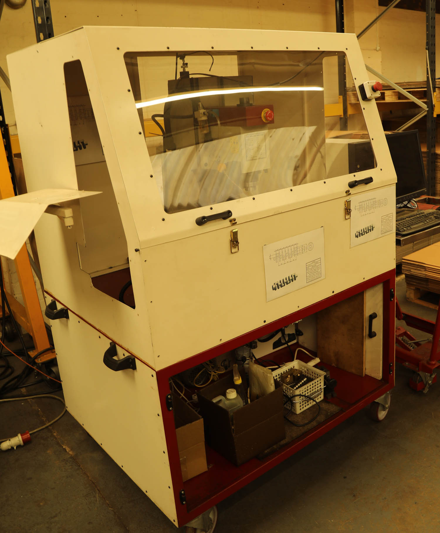
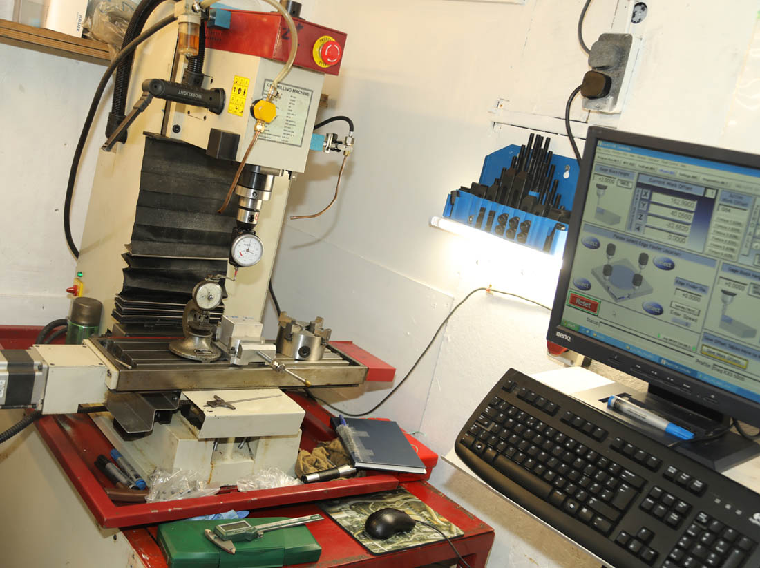
Not easy to see - but lurking beneath the extremely well built platform and full enclosure you can see here, you can just make out the vertical column of a Sieg KX3 CNC Mill. The stand and covers had been custom built for the machine - as this was the demo machine for my local tooling company, and it was requirement to have it fully enclosed when taking it to shows
Sieg CNC Milling Machine - A Chance Conversation Turned Good
I have probably mentioned a few times in past articles and Newsletters, that I have been keeping an eye out for a small CNC milling machine, to supplement my main CNC Lathe/Mill for small pure milling jobs, or second-op operations. As always, space was always my main issue with a milling machine - I do not have the luxery of large industrial premises any more, and any size of milling machine normally has a large footprint.
About 10 years ago, I was renting industrial premises with the opportunity to expand the area I was renting. At that time I had considering employing someone to do milling for me and looked at the smaller end of the industrial CNC milling machine market. Coming out favourite was definitely the Haas Mini Mill - and although not cheap (about 5 years ago when I last looked they were starting at about £30k + VAT for a bare minimum spec machine, where you could then purchase 'moduled' upgrades) - they did seem to offer good value for money vs quality. Since that time, aspirations have changed (as for many people post-Covid), and I am no longer in those premises - and think I have realised I would rather not have the additional stress of employing someone else, and having to keep a machine fully occupied.
All that said, I still had that 'itch I could not scratch' - as there had been so many times where I was working on a new item - where 80% of the manufacturing I could do on my Emco lathe/mill, but a vertical CNC mill would have been needed for just one simple operation or more.
Therefore, in the last 5 years, I had more than once spent time investigating what was available in the CNC market for small 'hobby style' vertical mills, that might be practical to go in the corner of a small workshop, and have a footprint no larger than 1 metre x 1 metre (knowing the slide table may extend past this).
And what I can tell you from my own experiences over a two years period - well at least in the UK hobby/small pro market . . . there seems to be almost nothing!
I did see that their is a nice, smallish, machine mill available in the US, the Tormach PCNC 440 benchtop mill - and I did make enquiries a couple of years ago - but I realised that at the time, it was touch and go if I could fit even that in the available space - and although reasonable value, by the time I had bought a toolchanger, some basic tooling and added in shipping and import duty, I would have been looking at the £15k mark easily - a reaonable investment for the small amount of work I was likely to get time to do on it.
My Local Tool Company To The Rescue
Anyway time moved on from those initial searchs, 2 or 3 years ago, but i still had an itch I could not scratch.
Then a chance conversation with one of my favourite local tool companies - Arc Euro Trading, in Syston, Leicester (https://www.arceurotrade.co.uk/ ) - threw up another option .. . and one that had much more promise!
Arc Euro are one of these small homegrown companies that bring in smaller machine tools and equipment from mainly offshore companies, such as China - but nothing wrong with that - the quality vs cost of most of these parts are fantastic, and they have a large following, catering for the occasional engineering and Model Engineers mainly, I believe.
However - they are also really helpful and courteous folks, and I have been using them for a number of years - often just nipping in, to buy the odd 5c Collet or similar, when I find a size I havent got.
Well, they also bring in a number of good value, small, Chinese
milling machines - and I know that some years ago, they did talk to one of their suppliers about a small CNC mill, and did bring a handful in to the UK I gather, but this was some years ago.
So last Summer 2022, while collecting some tools for the Emco, I happened to mention this again to Ian, their very friendly manager. I asked if there was any chance they may do so again - which unfortunately did not look likely, so I quizzed if they might know anyone that was selling one? It was then that Ian mentioned that they still had their original 'Demonstration' model in their own small workshop in the back, and actually, was thinking of clearing that workshop in the near future - so did I want to take a look?
The result of this was ultimately - I became the proud owner of an only very lightly used Sieg KX3 CNC Mill, as you in the pictures here!
As first shown to me - as in the top photograph, because it was their demonstration machine, it had had a purpose built stand and enclosure built around it - so that it would be 'safe' when taken to model engineerings shows and the like.
Other than a layer of dust over everything - as it had probably not been turned on since they last took it to a show (I gather at least 5 years ago, maybe more), it looked in extremely good condition, I gather it had only been used for light demonstrations - borne out by the small decoratively milled samples in one of the boxes under the bench.
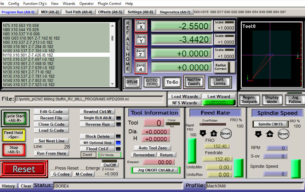
A week or so later I was given a demonstration of the machine in action - it uses the popular G-Code Software 'Mach-3 Mill', running from a simple Desktop PC anc screen (which Ian told me would come wtih the machine!) . . .and I bought it there and then on the spot!
As their plans had changed and they no longer intended to retail these CNC mills, they were happy to pass it on to someone - the only criteria being that I need to take it 'Lock, stock and barrel' . . . i.e. take it all away, so they can clear the space in their workshop and not have to worry about doing that themseves.
Likewise, I did not mind a couple of weeks of gruntwork moving it all out, using my trusty VW transporter van - given that it was offered to me at such a modest price, and at just a fraction of the cost I had previously been quoted on other machines - It meant I was not too concerned about it having to pay its keep . . . I could just install it at my leisure, and learn how to use it and setup, when I got time..
So, I went ahead and purchased, and Ian and his team were very helpful on their end, dismantling the cover and unbolting the machine from its stand., so I could take it away in instalments. Luckily they had suitable pallet trucks and the like for loading into my van . .. so I was able to move out the mill and all the perhiperal stands, PC and component parts over a 2 week period.
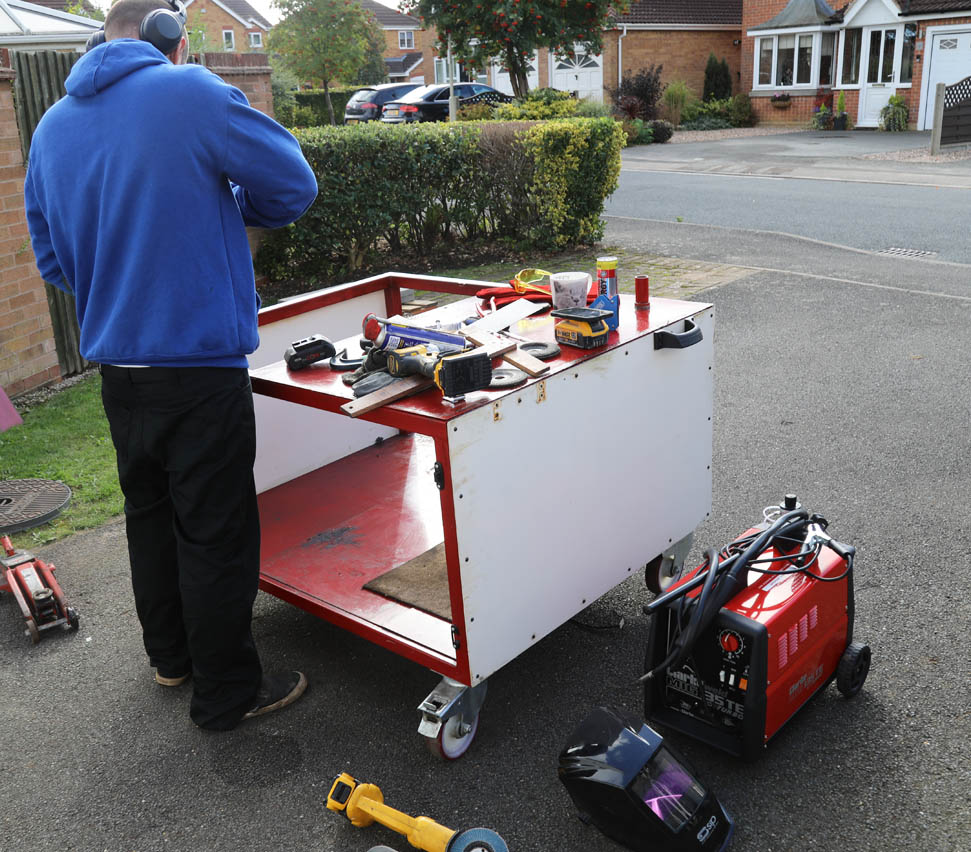
Part of the deal for getting the machine at such a reasonable price - was that I had to take and collect everything that was part of the machine setup - including the purpose built trolley platfom and cover. This must have cost a fortune to have made originally - as it was a work of art and must have weighed 150 kg on its own!, but unfortunately it was far too big for the small area I had reserved for it in my workshop. Therefore, here you can see a friend helping out for a day - and getting ready to cut down the lower trolley portion - so it can then be re-welded as a much slimmer unit.
Unfortunately, this meant the elaborate, windowed, top cover could no longer be fitted - but that now forms a very nice storage area/greenhouse in my garden!
After a lot of cleanup and painting preperation work, in my small secondary workshop shed - a couple of friends and I were able to 'trolley' the CNC SIeg into the shed . . . unfortunately at this stage it proved too heavy to lift up onto the newly 'slimmed down' base table . . . so it spent a couple of weeks sat on slabs, while I arranged for borrowing a suitable hydraulic lift table
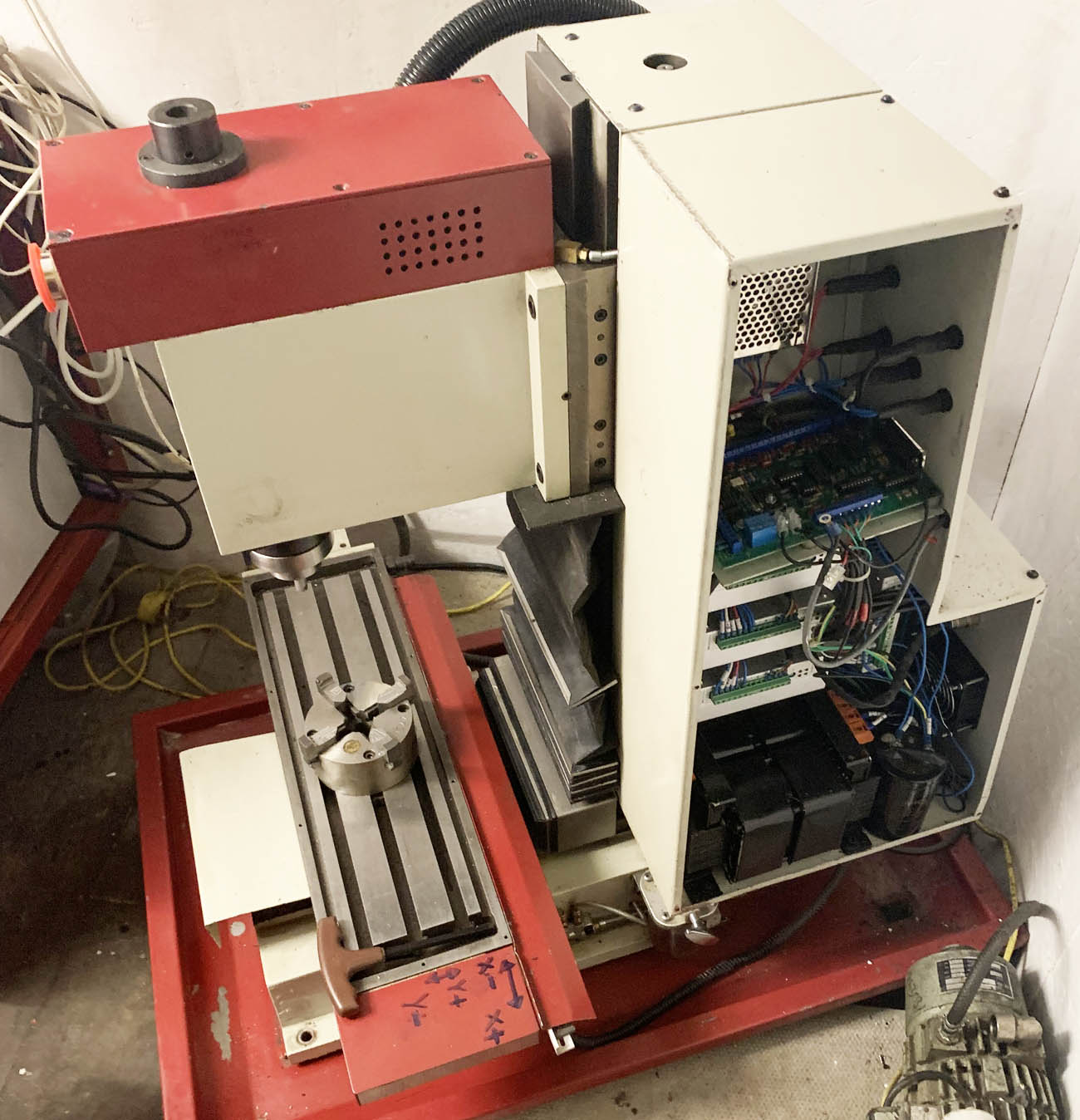
Axis Issues - Lets Start Removing Panels
While the machine was still on the workshop flloor (well actually about t a foot off the floor - mounted on concrete slabs) - I decieded to try and run the software and check everything was still functioning ok, but unfortunately not - one axis had gone A-Wall. Eventually, I resorted to removing side panels and getting into the guts of the machine . . . This seems a familiar process for me now . . . particularly since, just like the Emco . . . I have not got a clue what I am looking at!
Prep and Gruntwork
A friend and I had already spent a couple of weeks preparing the workshop area it was going to reside in (a workshop/shed at the tback of my property), so moving it into its new location - while not straightforward, and requiring the gruntwork of 3 people, only took a day or so of effort.
Getting it down the side of the property - iwth only a slab walkway was - ehh interesting with lots of anglo-saxon expletives from myself, as room was tight in a coupld of places . . .and we only had room for small rollers and steel rolling plates.
Unfortunately, although we were able to get the mill machine into its new workshop location, and propped up on concrete slabs about a foot off the ground - to get it onto the newly cutdown steel workbench was not possible with just our manhandling and jacks . . . it was just not safe enough . .. I guess the Sieg Mill must weight a good 400 or 500 pounds and the jacking equipment I had to hand would only lift the machine to about 6 inches short of the new workbench height.
However, Arc Euro came to hte resue again and lent us one of their hydraulic tables, which was small enough to get into the wokshop space, and strong enough to lift the Sieg to about 2 inches from the tabletop. A bit of additional jacking and wooden blocks was required to bridge the final gap . . . but eventually it was up on the table, secure and bolted down securley - good stuff!
Maybe It is This Wire??
Having followed different wires through to differnt areas of the machine, I evenually concluded that the most likely problem was the wires leading off the control block ringed in the photo above, as there looked like there may be a loose connection on the other end. Unforunately - not being a well known machine - finding anyone to advise me on the wiring was not simple .. .this photo was eventually sent to a very nice ex-owner I fouund on the web!, who very kindly dug out his own photos from when he had a similar machins a few years ago. - It turned out, it was these wires at fault, and luckily - fixed!
Not Working As It Should:
However, that is jumping ahead just a bit. Going back a couple of weeks - as it was when first moved into the shed on concrete slabs. I decided it would be a good idea to try and run the machine, as initially moved in, to check everything was still working as per the demo I had at Arc Euro.
Starting a machine for the first time, when you are not really familiar with the software is always a bit nervie wracking, but in this case I felt very out of my comfort zone, having never used Mach 3 software, and trying to remember the instructions Ian gave me when he gave me the demo.
Never the less, evertying on the software loaded ok (by the way - I bought a full Mach3 mill software licence . . .they are not expensive), but although I got the 3 axis moving ok, I could not start the main spindle motor.
To cut a long story short - it took on and off, the next week of poking about and eventually removing electrrical panels, and tracing wires and wiring looms between different areas - before I figured that maybe one pair of wires may have a bad connection - although still connected, of sorts. I tired to seek out expertise on the Web, but little is written about these machines .. .and what I did find seems to have been written by very entuiastic and intelligent hobbyist CNC machine builders . . . I felt very much out of my depth. Eventually I did find someone helpful who owned a similar machine some years ago.
Although he had not had my problem - he still had photos of his own electriclal connections . ..and gave me some confidence the wires I were looking at had come loose and needed attention. So with trepidation I put the wires where I thought they should have been (no doubt knocked out by all the manhandling of the mill into its new premises) . . . and bit the bullet and turned the machine on again . ..and turned on the main spindle - Wahhay . . .fthis time it started wtihout issue, another little glitch resolved, and the machine was now fully operational, even if I did not have a clue how to operate it!
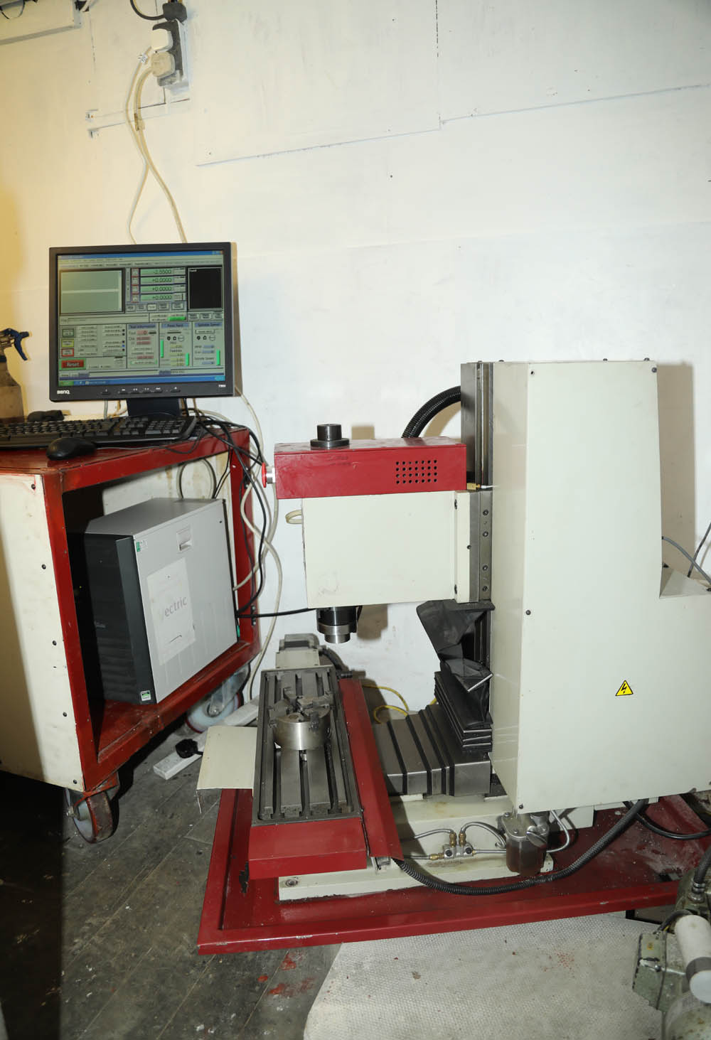
Finally In Position And Ready To Go
By this time it is late Summer 2022 - and the inside of this small workshop/shed has not looked so clean and roomy in years!. Along with the help of a friend, we had spent a couple of days cleaning out this area of the shed - double lining and insulating it (to make it more bearable in the cold) and finally giving it a coat of paint to make it look brighter.
As you can see - the cut down machine stand is still quite substantial and heavy - but much slimmer than it was 6 weeks before. Being substantially built - it provides an excellent base for the Mill machine, with desktop PC and small coolant compressor both safely tucked away underneath
Lets Make Something - Ehhh, Well Maybe Not Just Yet. . .
So, with the machine finally setup on its newly cut down - but still very robust workbench (which is also on large castors - so it can still be moved slightly if required) - it was finally operational, and setup in it s new location - looking all sparkly and spacious.
At this stage - probably late October by this time, it would have been nice to have a go at making something, and I had a couple of jobs in mind, which would give me a chance to learn the software and test my milling G-Code skills (which frankly - are close to non-existant!).
However, first - I had to get to grips with the rudiments of Mach3 Mill software and most importantly first - learning to do some tool setup.
The Sieg KX3 has an R8 spindle - which is one of the well known smallish spindles, fitted to this size of machine - along with Morse taper and 5c (which my Emco uses for its main spindle).
The machine came with a small selection of collets and a few milling tools, but over the September to December 2022 period, I settled on an initial array of tools and cutters I thought I would need. As always, the cost of this setup soon started to amount to a substantial amount . . . but that is to be expected, and as I have said before - the initial purchase price of the machine being so reasonable - meant I had a small budget available for doing just this. So by the middle of November I was just about tooled up to a level where I could consider a first machining job . . . but first I needed to work out how I was going to setup these new tools - which meant trying to learn the Mach3 Tool Offset functionality, and setup a tool Table.
More of that in Part 2 of this article . . .
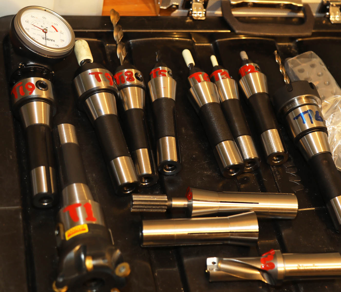
And of Course - Putting Some Tooling Together
Here you see a selection of milling tools, mounted on R8 spindles. Some of the R8 arbors are collets, some are fixed tool holders and others are 'ER' type collet holders. The latter type are my favourite as they can have a tool mounted and locked - and not require the offsets setting again each time the arbor is mounted. Note the lovely Sandvik 5 insert fly cutting tool in the lower left corner - I much prefer paying the extra money for solid carbide tools whenever possible - rather than HSS - particularly when, like with the KX3 mill, it does not have full 'Coolant Flood' facility. HSS tools can quickly burn out on a production run
Sieg KX3 - Learning Offsets And Edge Finding
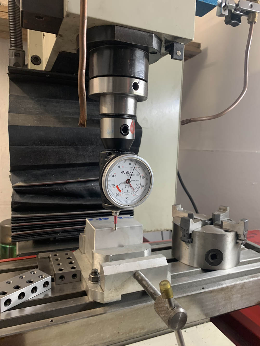
With the CNC Mill now setup - next task was learning the rudiments of MAch3 Mill software - so I could learn how to set the tool offsets and Edge Finding.
Here you see me trying to find the X and Y Axis edge of an alloy block, which will be machined as a jig for a trial job. I am using a Haimer Edge finder - which although it has only one dial - allows movement in all 3 Axis directions - a wonderful tool. Notice the little red piece on the shaft of the probe - that is a glass mid-piece, designed to smash if you have finger trouble and smash the tip into the workpiece too hard - hopefully saving the main tool!
(Click on pictures for closeups)!
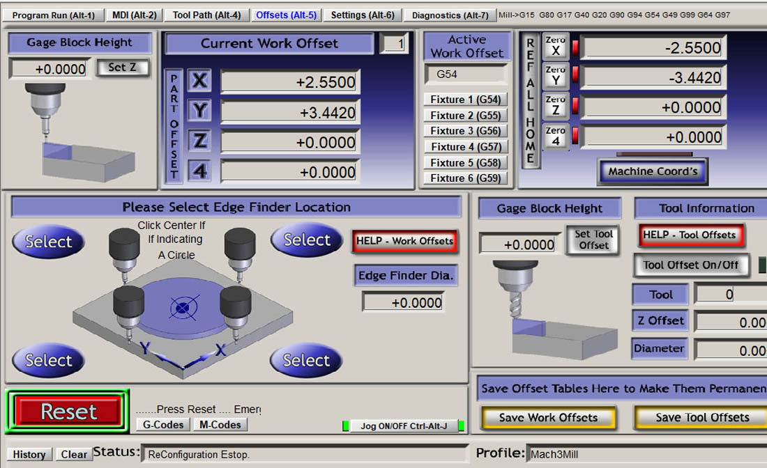
Mach3 Mill Software - Getting To Grips With It
On first impression - the Mach3 mill software that came wtih the machine looks quite dated, now - with its screen layout and display looking about 15-20 years old . . . but dont let that put you off - it seems to be very stable and is very popular with smaller hobbyist machines. It also seems to have a lot of functionality and 'canned' subroutines specifically for milling, which I havent got round to exploring yet.
In fact, at this time - a couple of smaller production jobs have just allowed me to wok out the bare essentials of running a program and tool changing . . . and of course - how best to stop the machine quickly when I realised I have screwed up and am trying to avoid a collision!
First Jobs and Learning How to interact wtih CAD-CAM software
<<<<<June 2023 - This will probably be a future article . . . >>>>>
Be Bye Delapena Honing Machine!
Well, with space being limited - and the footprint of the Sieg KX3 measured last Summer, it was with heavy heart I realised that my faithful old Delapena Autohone had to go . . . as it was taking up part of the same space the Sieg would need.
This has been a great machine for honing Norton BigEnds and rocker bearings - but I realise I am only using it on rare occasions - and it was taking up too much space for this luxery. Luckily a good friend of mine had been looking for one - so I was able to pass on the machine in fully working condition, including a large collection of honing bars. And although it is unlikely I can offer a honing service for customrs any more - I am told I can pop round to use it for my own needs in the future.
As you can see my mate came well equiped with his own pretty substantial lifting equipemnt . .. and a rather large trrailer to put it on!
Other Recent Equipment Issues and Changes
<<<<<June 2023 - Still updating, come back in a week or two! >>>>
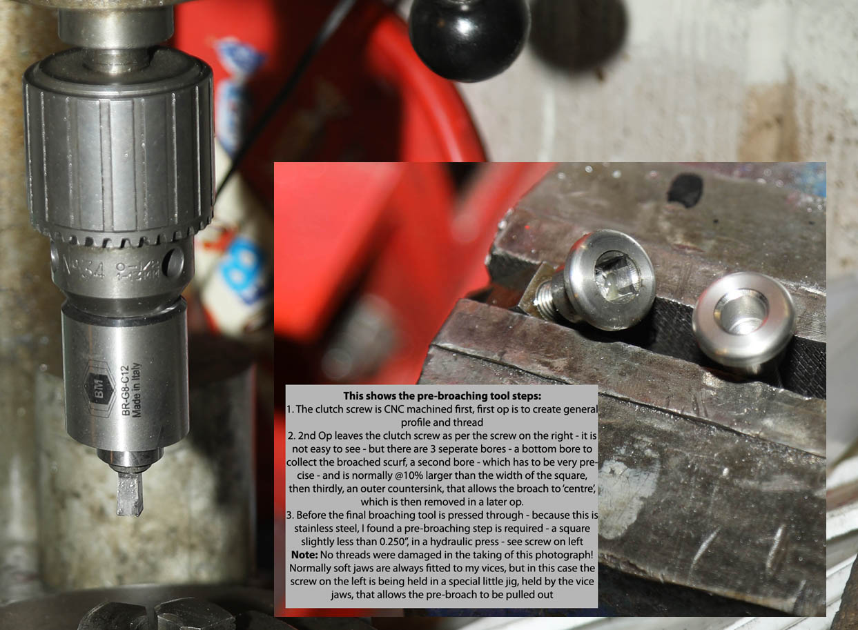
Broaching - One Of The More Unusual Engineering Tasks
I was recently back doing a batch of items that require broaching - a task I dont really enjoy much -
.But interesting in its own right. If I remember, I will cover it in the next tooling article.
Click on photo above to see a larger version and see the broaching tool and text